Strange VPN behaviour between Juniper ISG and ASA

Always something new what is not working, this time a site-to-site VPN tunnel between a Juniper ISG 2000 and a Cisco ASA 5520. After the initial set-up what a colleague did everything seemed to work fine with the VPN, the tunnel come up and communication was possible. What my colleague not did was to do some intensive testing and check in detail the configuration.

The problems began ones these VPN tunnels were used for production traffic, they worked fine for some hours or maybe days but then suddenly you were not able to send or receive any data over the tunnel and mostly it happen over night where it was difficult to troubleshoot. In the beginning everybody said that it was a problem within the internet but when it happened three or four times a week I got suspicious that its something wrong with the boxes or even configuration.

First thing was to check the configuration and quickly I found a difference in the IPSec Phase2 default timers, the Juniper uses 1 hour and Cisco has 8 hours. I was happy and thought I found the reason for the connectivity problems but then two days later it happened again… 🙁

There where some strange syslog messages about anti-replay checking failed:

ASA-4-402119 IPSEC: Received an ESP packet (SPI= 0xFBEFD496, sequence number= 0x1C24) from 80.210.78.10 (user=80.210.78.10) to 31.217.30.132 that failed anti-replay checking.

These messages always came when we had the connectivity problems and that could be only now the last reason. I have to say I didn’t really found much but there were some articles that Juniper doesn’t support Cisco Anti-Replay checking and that you need to disable that on the Cisco side.

Here a release note I found from Juniper but it’s about Cisco’s GET VPN:

http://www.juniper.net/techpubs/en_US/junos11.1/information-products/topic-collections/release-notes/11.1/index.html?topic-53319.html

In the end that was the only thing I found and I thought give it a try and disable the anti-replay checking on the ASA when we had the problems again. I did so I waited until the problem happened again and disable the anti-replay checking with the following command:

crypto ipsec security-association replay disable

It’s global command were you disable the checking for the whole device. Here some more information:

http://www.cisco.com/en/US/docs/security/asa/asa81/command/ref/c5.html#wp2200043

When I disabled the checking the communication was suddenly possible again and since then the problem never happened again so the anti-replay checking was the cause of the connection problems between the Juniper and the Cisco. Always something new to learn 🙂
Cisco ASA TCP Syslog Problem

I ran today into a big problem with configuring an TCP syslog server on an Cisco ASA.

logging host "interface_name" "server_ip" tcp/514

After I put in the configuration and someone from the server administration restarted the syslog server and suddenly the whole communication through the ASA stopped working completely.

I saw the following messages in the ADSM and quickly realised that this could be only caused by the TCP logging configuration.

%ASA-3-201008: Disallowing new connections

I didn’t looked before if the feature is disabled to block new connections when a TCP-connected syslog server is down. This is very important that you disable the feature before you configure TCP syslog servers otherwise you ran into the same problem like me.

Here the command to disable the feature:

logging permit-hostdown

In my case I just forgot to check before and will definitively remember for the next time 😉

First Hop Redundancy Configuration

The redundancy of the default gateway is important to keep network communication running in an case of an failure. I just want to show what choices you have there and how to configure these on a Cisco switch.

HSRP – Hot standby router protocol is standardized but licensed by Cisco Systems and very similar to the next one VRRP.

VRRP – Virtual router redundancy protocol is open standard and an alternative to Cisco HSRP both providing the same functionality. If you have network equipment from different vendors or want to keep open standard then use VRRP.

GLBP – Gateway load balancing protocol is Cisco proprietary and supports load balancing like the name already says.

HSRP configuration:

interface GigabitEthernet0/0
 ip address 192.168.0.2 255.255.255.0
 standby version {1 | 2}
 standby 1 ip 192.168.0.1
 standby 1 timers *hello* *dead*
 standby 1 priority *priority*
 standby 1 preempt
 standby 1 authentication md5 key-string *password*
 standby 1 track *interface* *value*
 standby 1 track *object* decrement *value*

Show command:

show standby brief

VRRP configuration:

interface GigabitEthernet0/0
 ip address 192.168.0.2 255.255.255.0
 vrrp 1 ip 192.168.0.1
 vrrp 1 timers {advertise *hello* | learn}
 vrrp 1 priority *priority*
 vrrp 1 preempt
 vrrp 1 authentication md5 key-string *password*
 vrrp 1 track *object* decrement *value*

Show command:

show vrrp brief

GLBP configuration:

interface GigabitEthernet0/0
 ip address 192.168.0.2 255.255.255.0
 glbp 1 ip 192.168.0.1
 glbp 1 timers *hello* *dead*
 glbp 1 timers redirect *redirect* *time-out*
 glbp 1 priority *priority*
 glbp 1 preempt
 glbp 1 forwarder preempt
 glbp 1 authentication md5 key-string *password*
 glbp 1 load-balancing *method*
 glbp 1 weighting *weight* lower *lower* upper *upper*
 glbp 1 weighting track *object* decrement *value*

Show command:

show glbp brief

The configuration can be also done on an SVI (VLAN) interface. You don’t need to configure everything, if you don”t set the timers to an custom value the default is taken same like with priority but if you change the timers you need to configure them both sides otherwise it will not work.

If you want to know more have a look at the Cisco First Hop Redundancy Protocols Configuration Guide

How correct network cabling should look like!

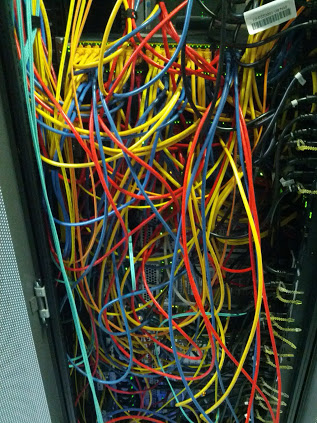
Network cabling in a data centre should not look like in the following picture 😉 there you have no structure and makes it difficult for someone else to look through how every server is connected.

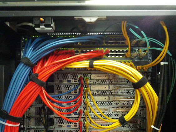
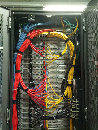
To make your life and work easier you just need to think before about what colors you use and then create an cabling standard what you always follow. Basically I choose three colors: blue, red and yellow. Yellow is management traffic, blue and red are main network connections (ports on the server must be teamed to have a redundant connectivity).

Here you clearly see that every server has an redundant connection to one of the switches in the rack. The blue cables are always connected to the top switch in the rack and the red to the second switch.

Here how the complete rack looks like, always look to keep it organised and follow your cabling standard.