Cisco ASA TCP Connection Flags

I got asked to look into a problem where two servers where not able to communicate with each other, ping didnt work and the application could not connect to the server. Firewall rules and routing was fine and my colleague spend already over an hour but couldnt find something. The first thing I asked, do you see a TCP connection? He told me yes over the ASDM logging I see something…. I double check and connect to the console and run:

show conn address 10.20.100.21

Show conn output:

TCP DMZ 10.10.127.29:2222 TRANSFER 10.20.100.21:42799, idle 0:00:00, bytes 0, flags saA
TCP DMZ 10.10.127.29:2223 TRANSFER 10.20.100.21:63554, idle 0:00:00, bytes 0, flags saA
TCP DMZ 10.5.63.29:2220 TRANSFER 10.20.100.21:59274, idle 0:00:00, bytes 0, flags saA
TCP DMZ 10.5.63.29:2221 TRANSFER 10.20.100.21:55782, idle 0:00:00, bytes 0, flags saA

I saw directly that the TCP connection was not open because the connection flag was “saA” what means outbound SYN was send and a connection is reserved but no SYN ACK came back. The problem in the end was that between these two servers was a VPN and that the IP network was missing in both crypto map’s what was then easy to find and solve in the end.

The command “show conn ?” give you enough information and when it comes to troubleshooting that you need to know basic troubleshooting skills because some stuff is not easy to find out over the ASDM and to use the command line instead.

Here the overview over the ASA TCP connection flags which are important to know or at least to know where to look them up 😉
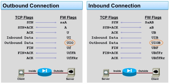
Here the document from Cisco: ASA TCP Connection Flags (Connection build-up and teardown)
 

Cisco ASA EtherChannel Interfaces

With the ASA version 8.4 Cisco introduced port-channels (ASA5510 or higher) what is a really nice feature because you can share the load over more interfaces. When it comes to a physical interface the incoming or outgoing traffic is processed through Fifo queues and RX/TX-rings per interface, when theses queues or rings are full nothing can pass through. So its not always related to CPU load of the device also the phsical interfaces are in the scope when it comes to performance. With port-channel you share the load over more Fifo queues and RX/TX-rings but keep in mind about the port-channel balancing mode.

Physical interface configuration

interface GigabitEthernet0/0
  description GigTrunk-Po1
  channel-group 1 mode active
  no shutdown
  exit

interface GigabitEthernet0/1
  description GigTrunk-Po1
  channel-group 1 mode active
  no shutdown
  exit

interface GigabitEthernet0/2
  description GigTrunk-Po1
  channel-group 1 mode active
  no shutdown
  exit

interface GigabitEthernet0/3
  description GigTrunk-Po1
  channel-group 1 mode active
  no shutdown
  exit

Port-channel configuration with VLAN sub-interfaces

interface Port-channel1
  no shutdown
  exit

interface Port-channel1.100
  description Server VLAN
  vlan 100
  nameif SERVER
  security-level 100
  ip address 10.1.0.254 255.255.255.0 standby 10.1.0.253
  mac-address 0a00.0a00.0011 standby 0a00.0a00.0021
  no shutdown
  exit

interface Port-channel1.200
  description Clients VLAN
  vlan 200
  nameif CLIENTS
  security-level 100
  ip address 10.2.0.254 255.255.255.0 standby 10.2.0.253
  mac-address 0a00.0a00.0011 standby 0a00.0a00.0021
  no shutdown
  exit

For more information read the Cisco ASA 8.4 Configuration Guide – EtherChannels

Cisco ASA Virtual Context Mode

A single Cisco ASA or a cluster of two ASAs can be partition into multiple virtual firewalls known as security contexts. Each context has it’s own independent firewall, with its own security policy, interfaces, and administrators. These contexts are similar to having multiple standalone ASA devices. In combination with failover groups you can run a ASA cluster in active/active state and utilize both devices. Don’t forget when a failover happens that both failover groups need to run on a single device, keep enough ressources free on both devices and do not oversubscribe too much.

You have to look because there are limitation what features are supported in context mode. In version 8 is unsupport to use dynamic routing protocols, VPN, Threat Detection and Quality of Service. In version 9 are some changes and now dynamic routing protocols (not RIP or OSPFv3) and site-to-site IPsec VPNs are supported.

Here the configuration example how to set-up an Cisco ASA 5580 with 10 Gigabit Ethernet interfaces.

Enabling the context mode

mode noconfirm multiple

Physical interface configuration

interface GigabitEthernet4/2 
  description Failover 
  no shutdown 
  exit 

interface GigabitEthernet4/3 
  description Stateful 
  no shutdown 
  exit 

interface TenGigabitEthernet5/0 
  description TeTrunk-1st 
  no shutdown 
  exit 

interface TenGigabitEthernet5/1 
  description TeTrunk-2nd 
  no shutdown 
  exit

Redundant interface configuration

interface Redundant 1
  description Redundant-Trunk
  member-interface TenGigabitEthernet5/0
  member-interface TenGigabitEthernet5/1
  exit

interface Redundant 1.800
  vlan 800
  description Link-Outside1
  exit

interface Redundant 1.801
  vlan 801
  description Link-Outside2
  exit

interface Redundant 1.100
  vlan 100
  description Link-Inside1
  exit

interface Redundant 1.101
  vlan 101
  description Link-Inside2
  exit

interface Redundant 1.500
  vlan 500
  description Link-Management
  exit

Here you need to start configuring the ASA failover settings. Like you see in the failover group configuration that I put group 1 to the primary device and group 2 to the seconday device for active/active set-up, when I create the virtual security context I join them to the different failover groups.

failover group 1
  primary
  polltime interface 1 holdtime 5
  exit

failover group 2
  secondary
  polltime interface 1 holdtime 5
  exit

failover

failover lan unit primary
failover lan interface failover GigabitEthernet4/2
failover interface ip failover 169.254.0.1 255.255.255.0 standby 169.254.0.2

failover link stateful GigabitEthernet4/3
failover interface ip stateful 169.254.1.1 255.255.255.0 standby 169.254.1.2

failover polltime unit 2 holdtime 6
failover polltime interface 1 holdtime 5
failover timeout 0:00:00

failover active

Failover configuration on the seconday device

interface GigabitEthernet4/2
  description Failover
  no shutdown
  exit

failover lan unit secondary
failover lan interface failover GigabitEthernet4/2
failover interface ip failover 169.254.0.1 255.255.255.0 standby 169.254.0.2

failover

copy running-config startup-config

Now you start to set-up the virtual contexts and add the interfaces I configured before

admin-context admin-asa-01

context admin-asa-01
  allocate-interface Redundant1.500 Link-Management
  config-url disk0:/admin-asa-01.conf
  join-failover-group 1
  exit

context virtual-asa-02
  allocate-interface Redundant1.800 Link-Outside1
  allocate-interface Redundant1.100 Link-Inside1
  config-url disk0:/virtual-asa-02.conf
  join-failover-group 1
  exit

context virtual-asa-03
  allocate-interface Redundant1.801 Link-Outside2
  allocate-interface Redundant1.101 Link-Inside2
  config-url disk0:/virtual-asa-03.conf
  join-failover-group 2
  exit

In the end save the configuration

write memory all

Afterwards you can change to the configured contexts with the command

changeto context virtual-asa-02

and start configuring your virtual firewalls.

Uptime – simple http monitoring utility

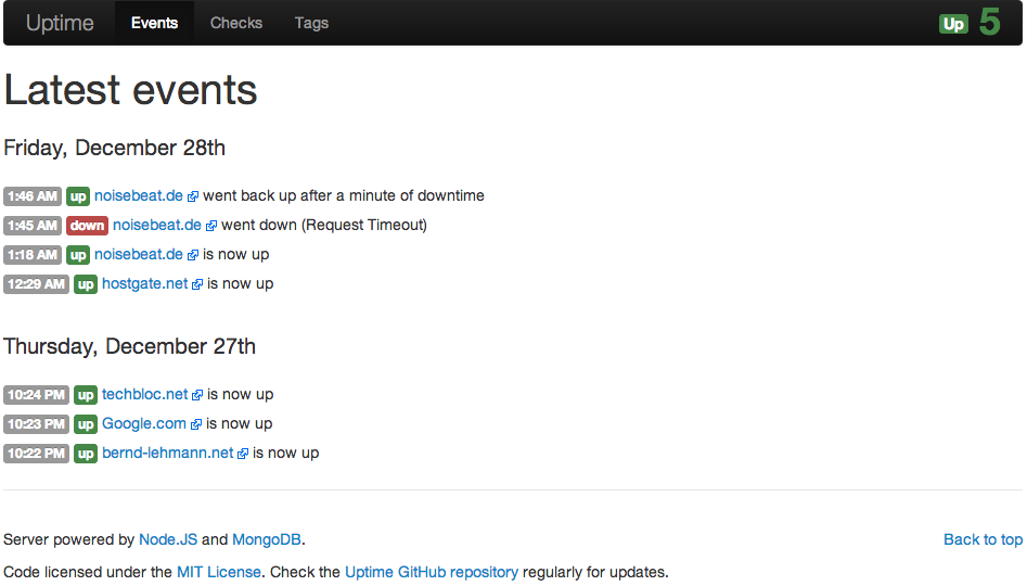
I found an very interesting http monitoring tool called Uptime using node.js and mongoDB. I directly installed Uptime on one of my Linux servers and from the first look I find it really cool 🙂 before you start you need to get node.js and mongoDB installed on your server and the rest is then very easy.

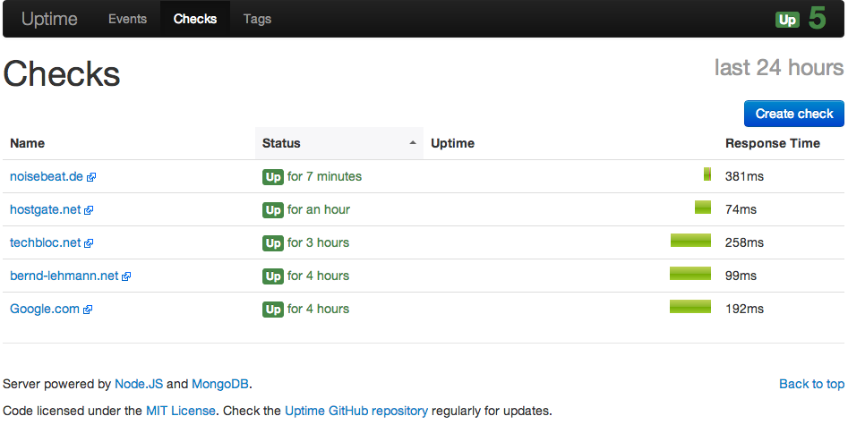
Ones the Uptime is running you can access the web interface and create the first checks, here some screenshots:

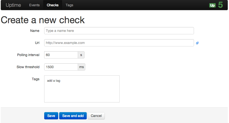
Here you create your http checks and define some settings:

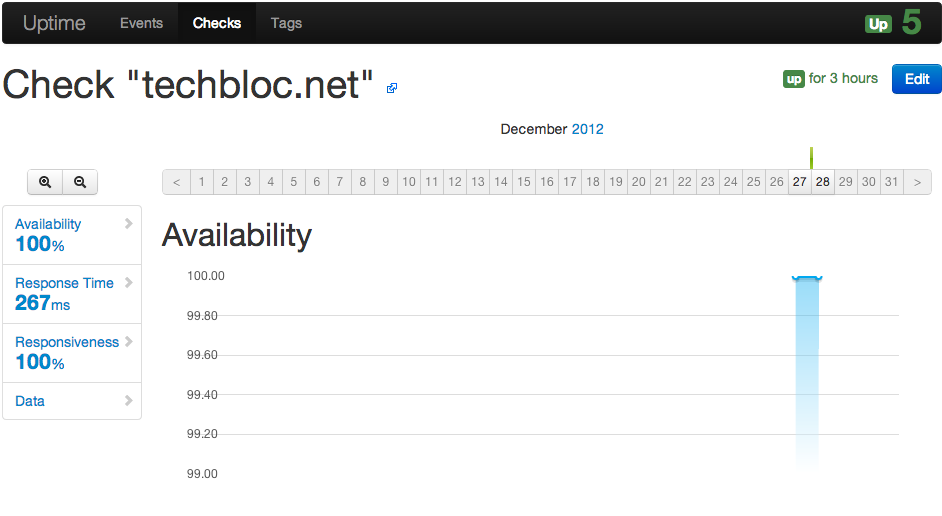
Detailed check overview with graphs:

If you are interested then have a look here: http://fzaninotto.github.com/uptime/

Cisco SSL VPN Configuration

At the moment I play around with Cisco SSL VPN (WebVPN) and here some steps how to configured these on an Cisco ASA. SSL VPN is on one hand the Cisco Anyconnect client and on the other an Clientless SSL VPN over a portal what is running on the ASA.

I will not go into much detail here, it’s more basic configurations steps you need to configure to get it running.

For a basic set-up we need two network objects

object network inside-subnet  
  subnet 172.16.0.0 255.240.0.0  
  exit

object network sslvpn-subnet  
  subnet 172.31.250.0 255.255.255.0  
  exit

Then we define the DHCP pool for Anyconnect connections

ip local pool SSLVPNClientPool 172.31.250.1-172.31.250.250 mask 255.255.255.0

We also need to make sure that Anyconnect clients communication with their original IP address and for that we need the following nat statement

nat (inside,outside) source static inside-subnet inside-subnet destination static sslvpn-subnet sslvpn-subnet

Here you select the Anyconnect package what you need to upload to your flash before and enable webvpn on your outside interface

webvpn  
  anyconnect image disk0:/anyconnect-win-2.4.1012-k9.pkg 1  
  enable outside  
  anyconnect enable  
  exit

In the SSL VPN client policy we define name server, domain name and DHCP pool. We also define here Anyconnect with ssl-client and the portal with ssl-clientless

group-policy SSLVPNClientPolicy internal 
group-policy SSLVPNClientPolicy attributes  
  dns-server value 172.16.0.12  
  default-domain value domain.com  
  address-pools value SSLVPNClientPool  
  vpn-tunnel-protocol ssl-client ssl-clientless  
  exit

We configure an SSL VPN tunnel group for remote access and set default policy to the SSL VPN client policy we configured in the step before

tunnel-group SSLVPNClientProfile type remote-access 
tunnel-group SSLVPNClientProfile general-attributes  
  default-group-policy SSLVPNClientPolicy  
  exit

Next, we define an external aaa server in my example an Windows Active Directory

aaa-server ldap-group protocol ldap
  aaa-server ldap-group (inside) host 172.16.0.12   
  ldap-base-dn OU=Departments, OU=DE, OU=Company, DC=domain,DC=com   
  ldap-login-dn cn=LDAPReader, OU=ServiceAccounts, OU=Company, DC=domain, DC=com   
  ldap-login-password secretpassword   
  ldap-naming-attribute sAMAccountName   
  ldap-scope subtree   
  server-type microsoft   
  exit

After we configured the external aaa server we need to link that in the tunnel group

tunnel-group SSLVPNClientProfile webvpn-attributes  
  group-alias SSLVPNClient enable  
  authentication-server-group ldap-group  
  exit

One of the last steps we enable the tunnel group within webvpn and configure sysopt permit-vpn

webvpn  
  tunnel-group-list enable  
  exit
sysopt connection permit-vpn

With the following command you can enable NTLM for a whole subnet if you use Windows IIS and integrate authentication

auto-signon allow ip 172.16.0.0 255.255.255.0 auth-type ntlm

That’s it, quite easy and clear setup over the command line, you can also click yourself through the ASDM but it will definitively take longer.