Cisco IP SLA Configuration

Not everyone knows how powerful the Cisco IP SLA feature is and here an short example what you can do with it.

At first you need to create the monitor in my case I just want to do basic ICMP testings to a specific IP address, you can of course also create other IP SLA operations in the end it just depends for what you need the IP SLA feature.

ip sla monitor 1
 type echo protocol ipIcmpEcho 192.168.1.2 source-interface FastEthernet1/0
 timeout 300
 frequency 3

Then you need to start the IP SLA monitor

ip sla monitor schedule 1 life forever start-time now

With the show command you can look if the tests are successful and then continue with the next step

show ip sla monitor statistics

Here you create the track definition

track 1 rtr 1 reachability

In the end you just need to add the track condition, in my example an static default route

ip route 0.0.0.0 0.0.0.0 192.168.0.2 track 1

When the IP 192.168.1.2 is reachable the static route is within the routing table of the Cisco router, when the IP is unreachable IP SLA deletes the static route from the routing table. I mostly use IP SLA to failover to an back-up internet connection because its very easy to configure.

More information you can find in the Cisco IOS IP SLAs Configuration Guide
GNS3 Network Simulator

Found something really cool today 🙂

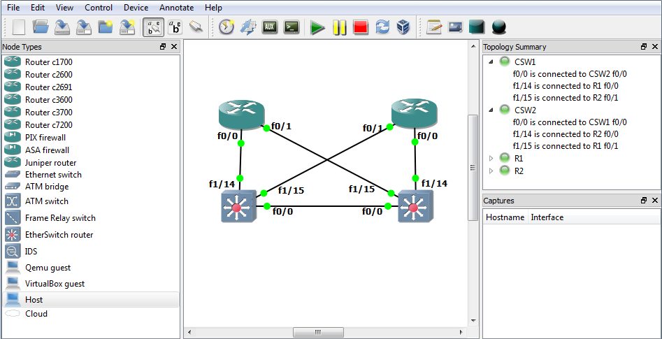
GNS3 is a graphical network simulator where you can set-up complex virtual networks and run Cisco and Juniper routers or switches. The best is that you can also integrate Qemu and Virtualbox into your virtual lab environment what I really love. You can easily test new configurations on devices without having to set-up all these in hardware.

The only little problem is that you need a quite power system to do all of that. Otherwise I tested GNS3 on an 3 year old laptop with Intel Core2Duo and 4 GB RAM and run up to 6 Cisco routers without any big problems what’s enough for me at the moment.

Ah I forgot, you can of course also use Wireshark to capture packets on an link between two devices.

Here the link to the website: www.gns3.net

Cisco Catalyst static CAM table entries

That’s maybe not interesting for everybody but when you use Windows Network Load Balancing in your network you should definitively configure static CAM table entries otherwise your VLAN will be flood with multicast traffic. You can create different VLANs for your Windows NLB instances to separate the traffic but that’s more an work around and with static CAM entries nicer from the design.

The static CAM table entries just restrict the multicast traffic to specific ports on your switch where your Servers are located and keep otherwise the network free.

On your router you will have an entry like that:

arp 10.0.0.100 0300.5e11.1111

An static ARP entry with an multicast MAC address

Now to restrict the multicast traffic you use the following command:

mac-address-table static 0300.5e11.1111 vlan 100 interface gi0/10 gi0/11

Which just means that the multicast traffic for VLAN 100 will be flood through the interfaces Gi0/10 and Gi0/11 and all other interfaces will not see the multicast traffic. Its a bit an administrative overhead and you have to think a little bit about that before you can implement but an clean traffic flow within your network.

If you want to read more about it have a look here: Catalyst Switches for Microsoft Network Load Balancing Configuration Example

Bug in Cisco ASA 8.4(4)1 found

I had a new office set-up in Sao Paulo/Brazil and found a bug what should be already fixed but still exists. You cannot access the management interface (inside) of your ASA when you come over an L2L/RemoteAccess VPN and your NAT statements overlaps the management ip address.

It’s an split-tunneling configuration where VPN traffic keeps the original IP address and when you go into the internet you will translated to the outside IP address. Have a look here at the cisco bug CSCtr16184

I used the following config what didn’t work:

nat (inside,outside) source static inside-subs inside-subs destination static vpn-subs vpn-subs

When you use the NAT statements described in the workaround it works fine:

nat (inside,outside) source static inside-subs inside-subs destination static vpn-subs vpn-subs route-lookup
nat (outside,inside) source static vpn-subs vpn-subs destination static inside-subs inside-subs route-lookup

This behavior should be already fixed in version 8.4(2.3) but in my 8.4(4)1 it still exists.

Here the bug details from Cisco:

To-the-box traffic fails from hosts over vpn after upgrade to 8.4.2.

Symptom:

After upgrading the ASA to 8.4.2, all management traffic to-the-box(including icmp/telnet/ssh/ASDM) from hosts over the VPN (L2L or Remote ACcess VPN) may fail when destined to the management-access interface IP address.

Conditions:

1. Issue is observed if ASA is on 8.4.2. Not observed on 8.4.1.
2. Users directly connected to the internal interfaces face no issues with icmp/telnet/ssh/asdm to their respective interfaces.

Workaround:

The problem can be traced to a Manual NAT statement that overlaps with the management-access interface IP address. The NAT statement must have both the source and destination fields. Adding the “route-lookup” keyword at the end of the NAT statement resolves the issue.

Cisco Catalyst SPAN and Remote SPAN Configuration

To analyze network traffic passing through ports or VLANs you can configure SPAN or remote SPAN to mirror the traffic to another port on the switch or on another switch that has been connected to a network analyzer. The network analyzer can be Wireshark or Riverbed Cascade Pilot what capture or analyze the traffic. Cascade Pilot is here quite interesting because you can filter the traffic before and then send it to Wireshark for a deep analysis.

Back to the configuration, SPAN mirrors traffic received or sent (or both) on source ports or source VLANs to a destination port for analysis. The SPAN session does not affect the switching of network traffic on the source. Except for traffic on the destination, ports do not receive or forward traffic there are shown as monitoring interfaces.


Configure local SPAN session:

Define the source interface which traffic you want to mirror

monitor session 1 source interface GigabitEthernet 0/41

or VLAN as source

monitor session 1 source vlan 500

Define the destination interface

monitor session 1 destination interface GigabitEthernet 0/10


Configure remote SPAN session (1st switch):

At first create an remote SPAN VLAN

vlan 2010
  name RSPAN_VLAN
  remote-span
  exit

Then like the local SPAN session define the source

monitor session 1 source interface gi 0/47

or VLAN

monitor session 1 source vlan 500

At the end of the configuration of the 1st switch you configure the remote SPAN VLAN as destination

monitor session 1 destination remote vlan 2010


Configure remote SPAN session (2nd switch):

Like on the other switch you need to create at first an remote SPAN VLAN

vlan 2010
  name RSPAN_VLAN
  remote-span
  exit

Then as source you configure the RSPAN VLAN

monitor session 1 source remote vlan 2010

In the end the destination interface

monitor session 1 destination interface gi 0/18

Important is to verify that the RSPAN VLAN is allowed between these two switches on thier Trunk Interfaces!


With the following command you can verify the monitoring session you configured

show monitor session 1