VMware NSX Edge Routing

I recently deployed VMware NSX (Software defined Network) in our datacentre.

About the NSX Edge cluster there are some some specific requirements when it comes to physical connectivity. All the information you find as well in the VMware NSX reference design guide.

On Cumulus Linux side I am using BGP in Quagga and the traffic is distributed via ECMP (Equal-cost multi-path) over multiple Edge nodes within NSX.

See below the overview:

Very important to have an dedicated VLAN per core switch to the Edge Nodes. In my tests it didn’t work with a shared VLAN via the Cumulus core, the BGP neighbor relationships were correctly established but there was a problem with the packet forwarding via the Peerlink.

Here the example Quagga BGP config from spine-1:

router bgp 65001 vrf vrf-nsx
 neighbor 10.100.254.1 remote-as 65002
 neighbor 10.100.254.1 password verystrongpassword!!
 neighbor 10.100.254.1 timers 1 3
 neighbor 10.100.254.2 remote-as 65002
 neighbor 10.100.254.2 password verystrongpassword!!
 neighbor 10.100.254.2 timers 1 3
 neighbor 10.100.254.3 remote-as 65002
 neighbor 10.100.254.3 password verystrongpassword!!
 neighbor 10.100.254.3 timers 1 3
 neighbor 10.100.254.4 remote-as 65002
 neighbor 10.100.254.4 password verystrongpassword!!
 neighbor 10.100.254.4 timers 1 3
 neighbor 10.100.255.2 remote-as 65001
 neighbor 10.100.255.2 password verystrongpassword!!

 address-family ipv4 unicast
  network 0.0.0.0/0
  neighbor 10.100.254.1 route-map bgp-in in
  neighbor 10.100.254.2 route-map bgp-in in
  neighbor 10.100.254.3 route-map bgp-in in
  neighbor 10.100.254.4 route-map bgp-in in
  neighbor 10.100.255.2 next-hop-self
  neighbor 10.100.255.2 route-map bgp-in in
 exit-address-family

ip route 0.0.0.0/0 10.100.255.14 vrf vrf_prod-nsx

access-list bgp-in permit 10.100.0.0/17

route-map bgp-in permit 10
 match ip address bgp-in

The second core switch, spine-2 looks exactly the same only different IP addresses are used.

More about my experience with VMware NSX will follow soon.

Ansible Playbook for Cumulus Linux (Layer 3 Fabric)

Like promised, here a basic Ansible Playbook for a Cumulus Linux Layer 3 Fabric running BGP which you see in large-scale data centre deployments.

You push the layer 2 network as close as possible to the server and use ECMP (Equal-cost multi-path) routing to distribute your traffic via multiple uplinks.

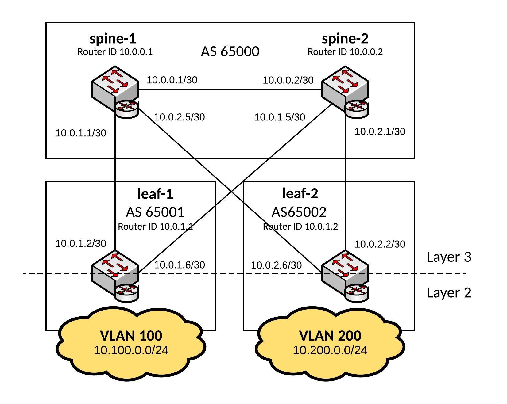
These kind of network designs are highly scalable and in my example a 2-Tier deployment but you can easily use 3-Tiers where the Leaf switches become the distribution layer and you add additional ToR (Top of Rack) switches.

Here some interesting information about Facebook’s next-generation data centre fabric: Introducing data center fabric, the next-generation Facebook data center network

I use the same hosts file like from my previous blog post Ansible Playbook for Cumulus Linux (Layer 2 Fabric)

Hosts file:

[spine]
spine-1
spine-2
[leaf]
leaf-1
leaf-2


Ansible Playbook:

---
- hosts: all
  remote_user: cumulus
  gather_facts: no
  become: yes
  vars:
    ansible_become_pass: "CumulusLinux!"
    spine_interfaces:
      - { port: swp1, desc: leaf-1, address: "{{ swp1_address}}" }
      - { port: swp2, desc: leaf-2, address: "{{ swp2_address}}" }
      - { port: swp6, desc: layer3_peerlink, address: "{{ peer_address}}" }
    leaf_interfaces:
      - { port: swp1, desc: spine-1, address: "{{ swp1_address}}" }
      - { port: swp2, desc: spine-2, address: "{{ swp2_address}}" }      
  handlers:
    - name: ifreload
      command: ifreload -a
    - name: restart quagga
      service: name=quagga state=restarted
  tasks:
    - name: deploys spine interface configuration
      template: src=templates/spine_routing_interfaces.j2 dest=/etc/network/interfaces
      when: "'spine' in group_names"
      notify: ifreload
    - name: deploys leaf interface configuration
      template: src=templates/leaf_routing_interfaces.j2 dest=/etc/network/interfaces
      when: "'leaf' in group_names"
      notify: ifreload
    - name: deploys quagga configuration
      template: src=templates/quagga.conf.j2 dest=/etc/quagga/Quagga.conf
      notify: restart quagga

Let’s run the Playbook and see the output:

[root@ansible cumulus]$ ansible-playbook routing.yml -i hosts

PLAY [all] *********************************************************************

TASK [deploys spine interface configuration] ***********************************
skipping: [leaf-2]
skipping: [leaf-1]
changed: [spine-2]
changed: [spine-1]

TASK [deploys leaf interface configuration] ************************************
skipping: [spine-1]
skipping: [spine-2]
changed: [leaf-2]
changed: [leaf-1]

TASK [deploys quagga configuration] ********************************************
changed: [leaf-2]
changed: [spine-2]
changed: [spine-1]
changed: [leaf-1]

RUNNING HANDLER [ifreload] *****************************************************
changed: [leaf-2]
changed: [leaf-1]
changed: [spine-2]
changed: [spine-1]

RUNNING HANDLER [restart quagga] ***********************************************
changed: [leaf-1]
changed: [leaf-2]
changed: [spine-1]
changed: [spine-2]

PLAY RECAP *********************************************************************
leaf-1                     : ok=4    changed=4    unreachable=0    failed=0
leaf-2                     : ok=4    changed=4    unreachable=0    failed=0
spine-1                    : ok=4    changed=4    unreachable=0    failed=0
spine-2                    : ok=4    changed=4    unreachable=0    failed=0

[roote@ansible cumulus]$

To verify the configuration let’s look at the BGP routes on the leaf switches:

root@leaf-1:/home/cumulus# net show route bgp
RIB entry for bgp
=================
Codes: K - kernel route, C - connected, S - static, R - RIP,
       O - OSPF, I - IS-IS, B - BGP, P - PIM, T - Table, v - VNC,
       V - VPN,
       > - selected route, * - FIB route

B>* 10.0.0.0/30 [20/0] via 10.0.1.1, swp1, 00:02:14
  *                    via 10.0.1.5, swp2, 00:02:14
B   10.0.1.0/30 [20/0] via 10.0.1.1 inactive, 00:02:14
                       via 10.0.1.5, swp2, 00:02:14
B   10.0.1.4/30 [20/0] via 10.0.1.5 inactive, 00:02:14
                       via 10.0.1.1, swp1, 00:02:14
B>* 10.0.2.0/30 [20/0] via 10.0.1.5, swp2, 00:02:14
  *                    via 10.0.1.1, swp1, 00:02:14
B>* 10.0.2.4/30 [20/0] via 10.0.1.1, swp1, 00:02:14
  *                    via 10.0.1.5, swp2, 00:02:14
B>* 10.200.0.0/24 [20/0] via 10.0.1.1, swp1, 00:02:14
  *                      via 10.0.1.5, swp2, 00:02:14
root@leaf-1:/home/cumulus#
root@leaf-2:/home/cumulus# net show route bgp
RIB entry for bgp
=================
Codes: K - kernel route, C - connected, S - static, R - RIP,
       O - OSPF, I - IS-IS, B - BGP, P - PIM, T - Table, v - VNC,
       V - VPN,
       > - selected route, * - FIB route

B>* 10.0.0.0/30 [20/0] via 10.0.2.5, swp1, 00:02:22
  *                    via 10.0.2.1, swp2, 00:02:22
B>* 10.0.1.0/30 [20/0] via 10.0.2.5, swp1, 00:02:22
  *                    via 10.0.2.1, swp2, 00:02:22
B>* 10.0.1.4/30 [20/0] via 10.0.2.1, swp2, 00:02:22
  *                    via 10.0.2.5, swp1, 00:02:22
B   10.0.2.0/30 [20/0] via 10.0.2.1 inactive, 00:02:22
                       via 10.0.2.5, swp1, 00:02:22
B   10.0.2.4/30 [20/0] via 10.0.2.5 inactive, 00:02:22
                       via 10.0.2.1, swp2, 00:02:22
B>* 10.100.0.0/24 [20/0] via 10.0.2.5, swp1, 00:02:22
  *                      via 10.0.2.1, swp2, 00:02:22
root@leaf-2:/home/cumulus#

Have fun!

Read my new post about an Ansible Playbook for Cumulus Linux BGP IP-Fabric and Cumulus NetQ Validation.

Cisco Policy Based Routing Example

This time not something about Cisco ASAs or Citrix NetScaler 😉 Here a little example how to redirect traffic with policy based routing.

The workstation in the client network 192.168.0.0/24 wants to access systems in the remote network 10.1.1.0/24, its just an example the remote network can be somewhere else. So I want to redirect the traffic to the Citrix Branch Repeater in the server network 192.168.1.0/24.

Here the configuration you need to apply on the router:

interface GigabitEthernet1/0/1
ip address 192.168.0.254 255.255.255.0
ip policy route-map client-policy-map

interface GigabitEthernet1/0/2
ip address 10.1.1.1 255.255.255.0
ip policy route-map remote-policy-map

interface GigabitEthernet1/0/3
ip address 192.168.1.254 255.255.255.0

ip access-list extended client-acl permit ip 192.168.0.0 0.0.0.255 10.1.1.0 0.0.0.255
ip access-list extended remote-acl permit ip 10.1.1.0.0 0.0.0.255 192.168.0.0 0.0.0.255

route-map remote-policy-map permit 20
 match ip address remote-acl
 set ip next-hop 192.168.1.200

route-map client-policy-map permit 10
 match ip address client-acl
 set ip next-hop 192.168.1.200

Here route maps with health checking over Cisco IP SLA, see my post: Cisco IP SLA Configuration

route-map remote-policy-map permit 20
 match ip address remote-acl
 set ip next-hop verify-availability 192.168.1.200 20 track 123

route-map client-policy-map permit 10
 match ip address client-acl
 set ip next-hop verify-availability 192.168.1.200 10 track 123

Citrix NetScaler (Update)

Almost 3 years ago I evaluated and implemented for my ex company F5 BIG-IP 8950 load balancer; now for my new company I start implementing Citrix NetScaler VPX for our Windows infrastructre (Lync, Exchange and Citrix). Here a short overview how it is integrate in the two data centre’s:

From the first look I like the NetScaler, the CLI is a bit easier to understand from what I think but will see how it goes over the next weeks regarding balancing compare to F5 😉

I like the policy based routing implementation on the Netscaler, here a short example:

add ns pbr mgmt-access ALLOW -srcIP = 10.1.0.200 -destIP = 192.168.0.1-192.168.0.254 -nextHop 10.1.0.254 -priority 10

Access to the 10.1.0.200 will be routed to the gateway 10.1.0.254 even you have a default gateway configured what shows to another direction.

In my set-up you need to configure policy based routing if server in the Windows backend network try to access virtual server IPs in the LB-Transfer network otherwise you have asymetric routing.

add ns pbr VIP-WIND-DC02 ALLOW -srcIP = 10.2.0.1-10.2.0.100 -destIP = 10.1.0.1-10.1.0.254 -nextHop 10.2.0.254 -priority 11

Cisco ASA TCP Connection Flags

I got asked to look into a problem where two servers where not able to communicate with each other, ping didnt work and the application could not connect to the server. Firewall rules and routing was fine and my colleague spend already over an hour but couldnt find something. The first thing I asked, do you see a TCP connection? He told me yes over the ASDM logging I see something…. I double check and connect to the console and run:

show conn address 10.20.100.21

Show conn output:

TCP DMZ 10.10.127.29:2222 TRANSFER 10.20.100.21:42799, idle 0:00:00, bytes 0, flags saA
TCP DMZ 10.10.127.29:2223 TRANSFER 10.20.100.21:63554, idle 0:00:00, bytes 0, flags saA
TCP DMZ 10.5.63.29:2220 TRANSFER 10.20.100.21:59274, idle 0:00:00, bytes 0, flags saA
TCP DMZ 10.5.63.29:2221 TRANSFER 10.20.100.21:55782, idle 0:00:00, bytes 0, flags saA

I saw directly that the TCP connection was not open because the connection flag was “saA” what means outbound SYN was send and a connection is reserved but no SYN ACK came back. The problem in the end was that between these two servers was a VPN and that the IP network was missing in both crypto map’s what was then easy to find and solve in the end.

The command “show conn ?” give you enough information and when it comes to troubleshooting that you need to know basic troubleshooting skills because some stuff is not easy to find out over the ASDM and to use the command line instead.

Here the overview over the ASA TCP connection flags which are important to know or at least to know where to look them up 😉

Here the document from Cisco: ASA TCP Connection Flags (Connection build-up and teardown)