First Hop Redundancy Configuration

The redundancy of the default gateway is important to keep network communication running in an case of an failure. I just want to show what choices you have there and how to configure these on a Cisco switch.

HSRP – Hot standby router protocol is standardized but licensed by Cisco Systems and very similar to the next one VRRP.

VRRP – Virtual router redundancy protocol is open standard and an alternative to Cisco HSRP both providing the same functionality. If you have network equipment from different vendors or want to keep open standard then use VRRP.

GLBP – Gateway load balancing protocol is Cisco proprietary and supports load balancing like the name already says.

HSRP configuration:

interface GigabitEthernet0/0
 ip address 192.168.0.2 255.255.255.0
 standby version {1 | 2}
 standby 1 ip 192.168.0.1
 standby 1 timers *hello* *dead*
 standby 1 priority *priority*
 standby 1 preempt
 standby 1 authentication md5 key-string *password*
 standby 1 track *interface* *value*
 standby 1 track *object* decrement *value*

Show command:

show standby brief

VRRP configuration:

interface GigabitEthernet0/0
 ip address 192.168.0.2 255.255.255.0
 vrrp 1 ip 192.168.0.1
 vrrp 1 timers {advertise *hello* | learn}
 vrrp 1 priority *priority*
 vrrp 1 preempt
 vrrp 1 authentication md5 key-string *password*
 vrrp 1 track *object* decrement *value*

Show command:

show vrrp brief

GLBP configuration:

interface GigabitEthernet0/0
 ip address 192.168.0.2 255.255.255.0
 glbp 1 ip 192.168.0.1
 glbp 1 timers *hello* *dead*
 glbp 1 timers redirect *redirect* *time-out*
 glbp 1 priority *priority*
 glbp 1 preempt
 glbp 1 forwarder preempt
 glbp 1 authentication md5 key-string *password*
 glbp 1 load-balancing *method*
 glbp 1 weighting *weight* lower *lower* upper *upper*
 glbp 1 weighting track *object* decrement *value*

Show command:

show glbp brief

The configuration can be also done on an SVI (VLAN) interface. You don’t need to configure everything, if you don”t set the timers to an custom value the default is taken same like with priority but if you change the timers you need to configure them both sides otherwise it will not work.

If you want to know more have a look at the Cisco First Hop Redundancy Protocols Configuration Guide
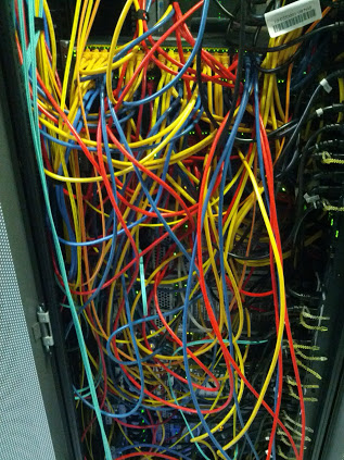
How correct network cabling should look like!

Network cabling in a data centre should not look like in the following picture 😉 there you have no structure and makes it difficult for someone else to look through how every server is connected.

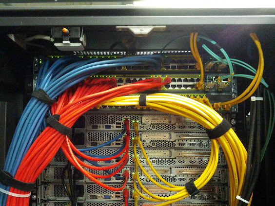
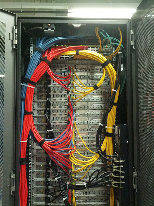
To make your life and work easier you just need to think before about what colors you use and then create an cabling standard what you always follow. Basically I choose three colors: blue, red and yellow. Yellow is management traffic, blue and red are main network connections (ports on the server must be teamed to have a redundant connectivity).

Here you clearly see that every server has an redundant connection to one of the switches in the rack. The blue cables are always connected to the top switch in the rack and the red to the second switch.

Here how the complete rack looks like, always look to keep it organised and follow your cabling standard.


Cisco IP SLA Configuration

Not everyone knows how powerful the Cisco IP SLA feature is and here an short example what you can do with it.

At first you need to create the monitor in my case I just want to do basic ICMP testings to a specific IP address, you can of course also create other IP SLA operations in the end it just depends for what you need the IP SLA feature.

ip sla monitor 1
 type echo protocol ipIcmpEcho 192.168.1.2 source-interface FastEthernet1/0
 timeout 300
 frequency 3

Then you need to start the IP SLA monitor

ip sla monitor schedule 1 life forever start-time now

With the show command you can look if the tests are successful and then continue with the next step

show ip sla monitor statistics

Here you create the track definition

track 1 rtr 1 reachability

In the end you just need to add the track condition, in my example an static default route

ip route 0.0.0.0 0.0.0.0 192.168.0.2 track 1

When the IP 192.168.1.2 is reachable the static route is within the routing table of the Cisco router, when the IP is unreachable IP SLA deletes the static route from the routing table. I mostly use IP SLA to failover to an back-up internet connection because its very easy to configure.

More information you can find in the Cisco IOS IP SLAs Configuration Guide

GNS3 Network Simulator

Found something really cool today 🙂

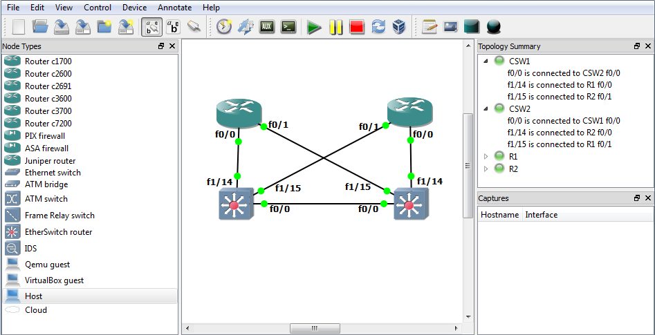
GNS3 is a graphical network simulator where you can set-up complex virtual networks and run Cisco and Juniper routers or switches. The best is that you can also integrate Qemu and Virtualbox into your virtual lab environment what I really love. You can easily test new configurations on devices without having to set-up all these in hardware.

The only little problem is that you need a quite power system to do all of that. Otherwise I tested GNS3 on an 3 year old laptop with Intel Core2Duo and 4 GB RAM and run up to 6 Cisco routers without any big problems what’s enough for me at the moment.

Ah I forgot, you can of course also use Wireshark to capture packets on an link between two devices.

Here the link to the website: www.gns3.net

Cisco Catalyst static CAM table entries

That’s maybe not interesting for everybody but when you use Windows Network Load Balancing in your network you should definitively configure static CAM table entries otherwise your VLAN will be flood with multicast traffic. You can create different VLANs for your Windows NLB instances to separate the traffic but that’s more an work around and with static CAM entries nicer from the design.

The static CAM table entries just restrict the multicast traffic to specific ports on your switch where your Servers are located and keep otherwise the network free.

On your router you will have an entry like that:

arp 10.0.0.100 0300.5e11.1111

An static ARP entry with an multicast MAC address

Now to restrict the multicast traffic you use the following command:

mac-address-table static 0300.5e11.1111 vlan 100 interface gi0/10 gi0/11

Which just means that the multicast traffic for VLAN 100 will be flood through the interfaces Gi0/10 and Gi0/11 and all other interfaces will not see the multicast traffic. Its a bit an administrative overhead and you have to think a little bit about that before you can implement but an clean traffic flow within your network.

If you want to read more about it have a look here: Catalyst Switches for Microsoft Network Load Balancing Configuration Example