Cisco ASA and IOS-XE embedded packet capturing

This is a short post about a step-by-step procedure to configure packet capturing on Cisco ASA or IOS XE using the CLI.

Cisco ASA embedded packet capturing:

access-list acl_capin extended permit ip host 217.100.100.254 host 10.0.255.254
access-list acl_capin extended permit ip host 10.0.255.254 host 217.100.100.254
capture capin interface inside access-list acl_capin

or

capture capin interface inside match ip host 10.0.255.254 host 217.100.100.254
[possible in asa 8.x and later]

Show captured packets:

asa-1(config)#  show capture capin

10 packets captured

   1: 15:11:12.760092       10.0.255.254 > 217.100.100.254: icmp: echo request
   2: 15:11:12.761755       217.100.100.254 > 10.0.255.254: icmp: echo reply
   3: 15:11:12.764196       10.0.255.254 > 217.100.100.254: icmp: echo request
   4: 15:11:12.765615       217.100.100.254 > 10.0.255.254: icmp: echo reply
   5: 15:11:12.768072       10.0.255.254 > 217.100.100.254: icmp: echo request
   6: 15:11:12.769354       217.100.100.254 > 10.0.255.254: icmp: echo reply
   7: 15:11:12.771612       10.0.255.254 > 217.100.100.254: icmp: echo request
   8: 15:11:12.773077       217.100.100.254 > 10.0.255.254: icmp: echo reply
   9: 15:11:12.775548       10.0.255.254 > 217.100.100.254: icmp: echo request
  10: 15:11:12.777150       217.100.100.254 > 10.0.255.254: icmp: echo reply
10 packets shown

asa-1(config)#

asa-1(config)#  show capture capinside detail

20 packets captured

   1: 15:11:12.760092 a000.0000.0001 a000.0000.0021 0x0800 Length: 114
      10.0.255.254 > 217.100.100.254: icmp: echo request (ttl 255, id 5)
   2: 15:11:12.761755 a000.0000.0021 a000.0000.0001 0x0800 Length: 114
      217.100.100.254 > 10.0.255.254: icmp: echo reply (ttl 255, id 5)
   3: 15:11:12.764196 a000.0000.0001 a000.0000.0021 0x0800 Length: 114
      10.0.255.254 > 217.100.100.254: icmp: echo request (ttl 255, id 6)
   4: 15:11:12.765615 a000.0000.0021 a000.0000.0001 0x0800 Length: 114
      217.100.100.254 > 10.0.255.254: icmp: echo reply (ttl 255, id 6)
   5: 15:11:12.768072 a000.0000.0001 a000.0000.0021 0x0800 Length: 114
      10.0.255.254 > 217.100.100.254: icmp: echo request (ttl 255, id 7)
   6: 15:11:12.769354 a000.0000.0021 a000.0000.0001 0x0800 Length: 114
      217.100.100.254 > 10.0.255.254: icmp: echo reply (ttl 255, id 7)
   7: 15:11:12.771612 a000.0000.0001 a000.0000.0021 0x0800 Length: 114
      10.0.255.254 > 217.100.100.254: icmp: echo request (ttl 255, id 8)
   8: 15:11:12.773077 a000.0000.0021 a000.0000.0001 0x0800 Length: 114
      217.100.100.254 > 10.0.255.254: icmp: echo reply (ttl 255, id 8)
   9: 15:11:12.775548 a000.0000.0001 a000.0000.0021 0x0800 Length: 114
      10.0.255.254 > 217.100.100.254: icmp: echo request (ttl 255, id 9)
  10: 15:11:12.777150 a000.0000.0021 a000.0000.0001 0x0800 Length: 114
      217.100.100.254 > 10.0.255.254: icmp: echo reply (ttl 255, id 9)
20 packets shown

asa-1(config)#
Browser capture:
https://10.255.1.203/admin/capture/capin

Download pcap:
https://10.255.1.203/capture/capin/pcap

Disable capture and remove access-list:

no capture capin
no capture capout
clear configure access-list acl_capin
clear configure access-list acl_capout

Cisco ASR embedded packet capturing:

ip access-list extended acl_cap
 permit ip any any
 permit icmp any any
 exit
 
monitor capture mycap access-list acl_cap 
monitor capture mycap limit duration 1000
monitor capture mycap interface GigabitEthernet3 both
monitor capture mycap buffer circular size 10
monitor capture mycap start
monitor capture mycap export tftp://10.255.1.87/mycap.pcap

Show captured packets:

rtr-2#show monitor capture mycap buffer dump
0
  0000:  A0000000 0004A000 00000001 08004500   ..............E.
  0010:  00640041 0000FF01 A9530A00 FF010A00   .d.A.....S......
  0020:  FF020800 0B62000D 00000000 0000001E   .....b..........
  0030:  72BDABCD ABCDABCD ABCDABCD ABCDABCD   r...............
  0040:  ABCDABCD ABCDABCD ABCDABCD ABCDABCD   ................
  0050:  ABCDABCD ABCDABCD ABCDABCD ABCDABCD   ................
  0060:  ABCDABCD ABCDABCD ABCDABCD ABCDABCD   ................
  0070:  ABCD                                  ..

1
  0000:  A0000000 0001A000 00000004 08004500   ..............E.
  0010:  00640041 0000FF01 A9530A00 FF020A00   .d.A.....S......
  0020:  FF010000 1362000D 00000000 0000001E   .....b..........
  0030:  72BDABCD ABCDABCD ABCDABCD ABCDABCD   r...............
  0040:  ABCDABCD ABCDABCD ABCDABCD ABCDABCD   ................
  0050:  ABCDABCD ABCDABCD ABCDABCD ABCDABCD   ................
  0060:  ABCDABCD ABCDABCD ABCDABCD ABCDABCD   ................
  0070:  ABCD                                  ..
...

rtr-2#show monitor capture mycap buffer
 buffer size (KB) : 10240
 buffer used (KB) : 128
 packets in buf   : 14
 packets dropped  : 0
 packets per sec  : 1
...

Disable capture and remove access-list:

monitor capture mycap stop
no monitor capture mycap
no ip access-list extended acl_cap
Ansible Interface Playbook (ios_config): Cisco interface config

Here an Ansible Playbook with three different examples how to configure Cisco router interfaces:

1. Static IP address configuration in playbook
2. Configuration comes out of Jinja2 template, can be run dynamic with variables
3. Loop in playbook configures multiple interfaces

There are some disadvantages to work with templates, if you use commands like “no shutdown” to enable the interface. They are not shown in the running-configuration which means Ansible will assume that the configuration is not matching and execute the template again.
Another disadvantage with templates is that you cannot run “before” or “after” commands to remove existing configuration all this needs to be implemented in your Jinja2 template.

Here the Ansible Playbook:

- name: Cisco interface config
  connection: local
  hosts: all
  gather_facts: false
  vars:
    cli:
      username: "{{ username }}"
      password: "{{ password }}"
      host: "{{ device_ip }}"
  tasks:
    - name: configure IP address
      ios_config:
        before: 
          - default interface FastEthernet1/0
        lines: 
          - ip address 10.1.1.1 255.255.255.0
        after: 
          - no shutdown
        match: strict
        parents: interface FastEthernet1/0
        provider: "{{ cli }}"

    - name: configure IP out of template
      ios_config:
        src: "interfaces.j2"
        provider: "{{ cli }}"

    - name: configure IP with loop
      ios_config:
        provider: "{{ cli }}"
        before:
          - "default interface {{ item.interface }}"
        lines:
          - "ip address {{ item.address }} 255.255.255.0"
        after:
          - no shutdown
        parents: "interface {{ item.interface }}"
      with_items:
        - { interface : FastEthernet2/0, address : 10.3.3.3 }
        - { interface : FastEthernet2/1, address : 10.4.4.4 }

Read my new posts about Ansible Playbook for Cisco ASAv Firewall Topology or Ansible Playbook for Cisco BGP Routing Topology.

Ansible Semaphore

I spend lot of time working with Ansible in the last weeks to automate the deployment of Cisco router or Cumulus switches. (Waiting for Ansible 2.2 to support Cisco ASA devices..)
Ansible is a great tool but if you have multiple YAML files and various roles it can get pretty messy and would be nice to have central tool to trigger your tasks and structure your environment variables or inventories.

I exactly found this tool with Ansible Semaphore: https://github.com/ansible-semaphore/semaphore

The install is pretty easy and provides an API to trigger your tasks remotely.

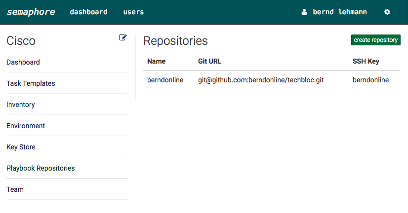
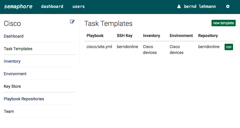
You can create different projects and include your Ansible YAML files.

screen-shot-2016-10-15-at-21-59-57

The source is a Git repository where your files are stored:

screen-shot-2016-10-15-at-21-58-18

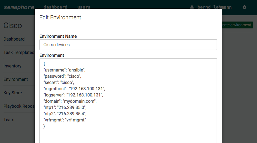
Here your environment variables:

screen-shot-2016-10-15-at-21-58-43

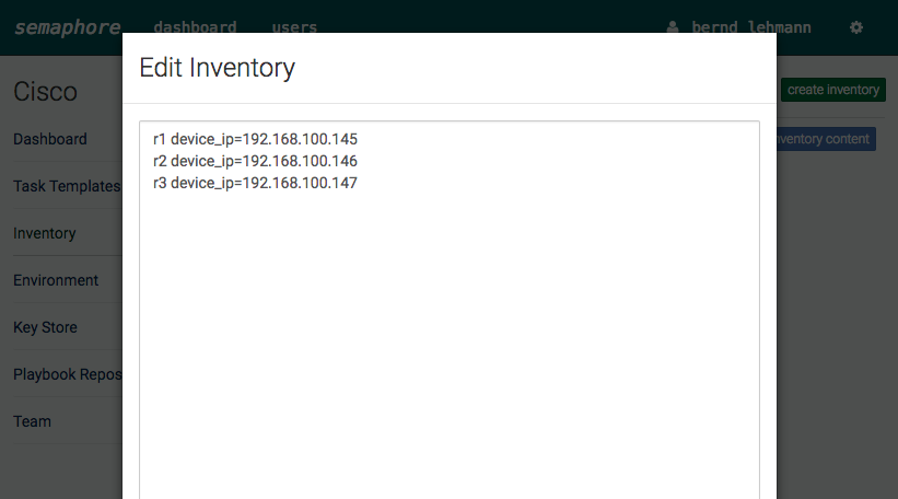
Inventory definition:

screen-shot-2016-10-15-at-21-59-02

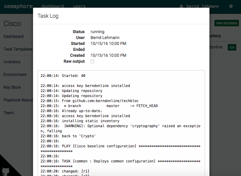
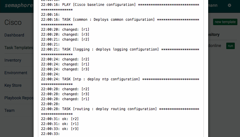
Finally the you can execute your Ansible YAML files via the Web UI or API:

screen-shot-2016-10-15-at-22-00-26

screen-shot-2016-10-15-at-22-00-53

Have fun playing around with Semaphore 🙂

Cisco IOS automation with Ansible

Bin a long time since I wrote my last post, I am pretty busy with work redesigning the data centres for my employer. Implementing as well an SDN Software-defined Network from VMware NSX but more about this later.

Ansible released some weeks ago new core modules which allows you to push directly configuration to Cisco IOS devices. More information you find here: https://docs.ansible.com/ansible/list_of_network_modules.html

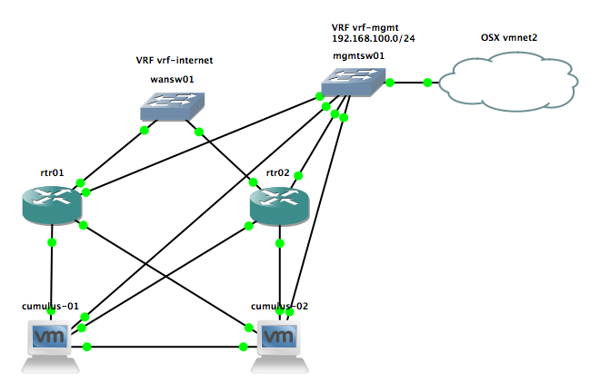
I created a small automation lab in GNS3 to test the deployment of configs via Ansible to the two Cisco routers you see below. I am running VMware Fusion and used the vmnet2 (192.168.100.0/24) network for management because I run there my CentOS VM from where I deploy the configuration.

Don’t forget you need to pre-configure your Cisco router that you can connect via SSH to deploy the configuration.

Here the folder and file script structure of my Ansible example, under roles you have the different tasks I would like to execute common and logging but as well dependencies writecfg which saves the running-config to startup-config:

site.yml
hosts
group_vars/all.yml
roles/common/meta/main.yml
roles/common/task/main.yml
roles/common/templates/common.j2
roles/logging/meta/main.yml
roles/logging/tasks/main.yml
roles/logging/templates/common.j2
roles/writecfg/handlers/main.yml

The site.yml is the main script which I execute with Ansible which includes different roles for common and logging configuration:

- name: Cisco baseline configuration
  connection: local
  hosts: ios 
  gather_facts: false

  roles:
    - role: common
      tags: common
    - role: logging
      tags: logging

In the hosts file, I define the hostname and IP addresses of my IOS devices

[ios]
rtr01 device_ip=192.168.100.130
rtr02 device_ip=192.168.100.132

The file group_vars/all.yml defines variables which I used when the script is executed:

---
username: "ansible"
password: "cisco"
secret: "cisco"
logserver: 192.168.100.131

Under the roles/../meta/main.yml I set a dependency on the writecfg handler to save the configuration later when I change anything on the device.

Under the roles/../tasks/main.yml I define the module which I want to execute and the template I would like to deploy

Under the roles/../templates/.. you find the Jinja2 template files which include the commands.

Under roles/writecfg/handler/main.yml is the dependencies I have with the two roles common and logging to save the configuration if something is changed on the router.

To execute the cisco-baseline Ansible script just execute the following command and see the result:

[user@desktop cisco-baseline]$ ansible-playbook site.yml -i hosts

PLAY [Ensure basic configuration of switches] **********************************

TASK [common : ensure common configuration exists] *****************************
ok: [rtr02]
ok: [rtr01]

TASK [logging : ensure logging configuration exists] ***************************
changed: [rtr02]
changed: [rtr01]

RUNNING HANDLER [writecfg : write config] **************************************
ok: [rtr01]
ok: [rtr02]

PLAY RECAP *********************************************************************
rtr01                      : ok=3    changed=1    unreachable=0    failed=0
rtr02                      : ok=3    changed=1    unreachable=0    failed=0

[user@desktop cisco-baseline]$

Read my new posts about Ansible Playbook for Cisco ASAv Firewall Topology or Ansible Playbook for Cisco BGP Routing Topology.

Cisco Policy Based Routing Example

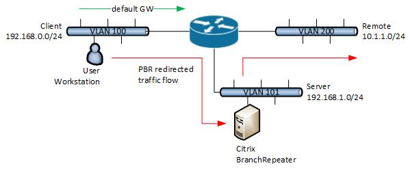
This time not something about Cisco ASAs or Citrix NetScaler 😉 Here a little example how to redirect traffic with policy based routing.

The workstation in the client network 192.168.0.0/24 wants to access systems in the remote network 10.1.1.0/24, its just an example the remote network can be somewhere else. So I want to redirect the traffic to the Citrix Branch Repeater in the server network 192.168.1.0/24.

Here the configuration you need to apply on the router:

interface GigabitEthernet1/0/1
ip address 192.168.0.254 255.255.255.0
ip policy route-map client-policy-map

interface GigabitEthernet1/0/2
ip address 10.1.1.1 255.255.255.0
ip policy route-map remote-policy-map

interface GigabitEthernet1/0/3
ip address 192.168.1.254 255.255.255.0

ip access-list extended client-acl permit ip 192.168.0.0 0.0.0.255 10.1.1.0 0.0.0.255
ip access-list extended remote-acl permit ip 10.1.1.0.0 0.0.0.255 192.168.0.0 0.0.0.255

route-map remote-policy-map permit 20
 match ip address remote-acl
 set ip next-hop 192.168.1.200

route-map client-policy-map permit 10
 match ip address client-acl
 set ip next-hop 192.168.1.200

Here route maps with health checking over Cisco IP SLA, see my post: Cisco IP SLA Configuration

route-map remote-policy-map permit 20
 match ip address remote-acl
 set ip next-hop verify-availability 192.168.1.200 20 track 123

route-map client-policy-map permit 10
 match ip address client-acl
 set ip next-hop verify-availability 192.168.1.200 10 track 123